

NTT DOCOMO Transport Network Upgrade Technology to Meet Diverse User Needs
Transport Network Transport Slicing SDN Controller
Tsuyoshi Yoshino, Kazuaki Yamabe and Tomoki Amano
Infrastructure Design Department Transport Design Office
Shotaro Kawakami
DOCOMO Technology, Inc. Core Network Engineering Division
Takashi Takehara
DOCOMO CS Chugoku, Inc. Network Operation Department
Shoichi Takashina
DOCOMO CS, Inc. Mobile Network Construction Department
Abstract
In recent years, NTT DOCOMO's transport network has been required to meet various user needs such as high-capacity data communications, low latency, multiple connections, and confidentiality among users.
To address these needs, NTT DOCOMO has been reviewing network topologies to reduce transmission delay values, logically partitioning network resources using transport slicing, and centrally managing, configuring, and changing communication paths using SDN controllers. This article describes these initiatives.
01. Introduction
-
With the introduction of the 5th Generation mobile communication system (5G) ...
Open

With the introduction of the 5th Generation mobile communication system (5G) and the development of the Internet of Things (IoT), NTT DOCOMO's transport network is required to meet diverse user needs such as high-capacity data communications, low latency, multiple connections, and confidentiality among users. To meet these demands, new technologies such as network slicing have been proposed and introduced onto the market, and NTT DOCOMO has been making various efforts with its transport network.
In addition, to achieve communications with high capacity and low latency, etc., it is necessary to select communication paths that meet these needs. However, as it is operationally difficult for maintenance personnel to control many communication paths individually, a centralized and efficient means of controlling them is required.
This article first provides an overview of the DOCOMO transport network, followed by a description of various initiatives (optimization of network topology*1, Segment Routing Traffic Engineering (SR-TE)/transport slicing, and introduction of Software-Defined Networking (SDN)*2 controllers).
- Network topology: Information related to the network configuration within a telecommunications carrier, such as host names.
- SDN: Software control of configurations and operations of equipment that make up the network.
-
A transport network includes a network consisting of Network Elements (NEs) ...
Open
A transport network includes a network consisting of Network Elements (NEs)*3 (Wavelength Division Multiplexing (WDM)*4, Fiber Termination Modules (FTMs)*5, etc.) that mainly handle the physical layer*6 and data link layer*7, as well as a network composed of NEs (routers, switches, etc.) that mainly deal with the network layer*8. This article focuses on the network layer.
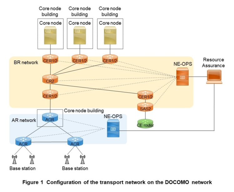
As shown in Figure 1, the DOCOMO network consists of two main types of transport networks: a network to efficiently accommodate many base stations (Access Router (AR) network) and a Backbone Router (BR) network to handle a large amount of traffic exchanged between buildings in which core nodes*9 are installed (hereinafter referred to as called “core node buildings”).
The AR network is responsible for efficiently accommodating base stations, which are installed over a wide area to expand the service area available to users, in core node buildings. The AR network consists of two types of NEs called Area aCcess Router (ACR) and Area aGgregation Router (AGR). The ACR is located above the base stations and is responsible for aggregating multiple base station areas and their communications and connecting them to the AGR. The AGR is responsible for aggregating each ACR and connecting it to the upper BR network. The NE OPeration System (NE-OPS )*10, which is responsible for monitoring, controlling and configuring ACR and AGR, is also on the AR network.
The NE-OPS of the AR network is connected to an external system called resource assurance*11, which performs simple controls such as listing monitoring information and checking equipment status.
The BR network is primarily responsible for data transfer between core node buildings, and transfers user and control traffic between the AR network and core nodes. The BR network consists of three types of NEs called Converged Edge Router 1/2 (CER1/2)*12, SAtellite Switch2 (SAS2)*13, and Core Router2 (CR2)*14. CER1/2 and SAS2 accommodate various systems, while CR2 forwards traffic inside the BR network from the accommodated systems. As with the AR network, NEs are controlled and configured by NE-OPS. Equipment is monitored using the resource assurance.
- NE: A generic term for the equipment that makes up a network.
- WDM: Wavelength division multiplexer.
- FTM: Wiring equipment that accommodates subscriber optical fiber lines.
- Physical layer: Defining physical connections and transmission methods, the first layer of the OSI reference model. The OSI reference model classifies and defines communication functions.
- Data link layer: Defining data transfer methods between directly connected equipment, the second layer of the OSI reference model.
- Network layer: Defining methods for transferring data through a network to destination equipment, the third layer of the OSI reference model.
- Core node: An upper-level node such as a call processing server or subscriber information management equipment.
- NE-OPS: A generic term for a system that monitors and controls NEs. Equivalent to an Element Management System (EMS).
- Resource assurance: External system that consolidates and manages monitoring of equipment operating status and alarm reporting status through data linkage with NE-OPS.
- CER1/2: An NE that accommodates users at the edge layer. Although two types of NE exist as equipment, CER1 and its successor, the CER2, are collectively referred to as CER1/2 in this article.
- SAS2: An NE that accommodates 1 Gbps or 10 Gbps users at the edge layer.
- CR2: An NE that transfers data in the network in the core layer.
-
3.1 Network Topology Optimization
Open
1) Network Topology of the AR Network
The AR network basically consists of a star topology*15 with multiple ACRs connected below the AGRs. On the other hand, a topology that directly connects adjacent ACRs to ACRs can also be considered, which avoids constructing long-distance transmission lines across buildings housing AGRs, reduces transmission line costs, and allows for flexible and easy network topology expansion when adding new ACRs.
In addition, redundant physical lines are used to connect ACR and AGR to increase network resiliency. Furthermore, since AGRs aggregate communications within each area and the communication impact in the event of failure is significant, redundant equipment allows communications to continue even if a piece of equipment fails [1].
2) Network Topology of the BR Network
Previously, a transport network called the IP router network*16 was used. However, the new BR network has been established as its successor. The IP router network used a two-star topology network configuration based in Eastern and Western Japan, as shown in Figure 2. NTT DOCOMO has been operating the IP router network since 2004, but the number of access layer equipment types has increased, and the network topology has become more complex as new NEs are built or added due to increased user demand.
The BR network has a newly revised topology, adopting a partial-mesh topology*17 in which the core layer is divided into multiple regional blocks and CR2s are placed in each block.
Regarding fault tolerance, in IP router networks, previously if a core layer NE failed, the edge layer NEs under it were also affected. However, partial-mesh topology enables the BR network to distribute the effects of core layer failures, thereby enhancing resilience to severe disasters. Each layer of the BR network consists of two sides, A and B. In the event of failure or maintenance on one side, communications continue on the opposite side.
On the BR network, all connections inside the core layer and between the core and edge layers are made up of 100 Gbps lines. In addition, 1 Gbps and 10 Gbps users are accommodated using edge layer SAS2, thereby eliminating the access layer that existed in the IP router network. This has reduced the number of network layers and reduced communication delays between NEs, which had been caused by going through multiple NEs.
Also, in IP router networks, communication between areas was always done through 2-star CRs located in the core layer, but in BR networks, communication can be done directly between areas that are housed in the same regional block. This has reduced the communication delay that occurred in IP router networks.
The core layer bundles 100 Gbps physical circuits together to form logical high-capacity circuits. The configuration also allows for the application of 400 Gbps physical circuits in preparation for further traffic growth in the future.

3.2 Introduction of SR-TE and Transport Slicing Technology
Network slicing is a technology that divides the same physical network into “slices” for each virtual network*18 requirement. To achieve network slicing from the mobile terminal to the core node, corresponding control is also necessary within the transport network. In this article, the technology that makes this possible is called transport slicing.
1) SR-TE
(a) Overview
Various methods for achieving transport slicing are currently under discussion, among which NTT DOCOMO has adopted a method using SR-TE. SR-TE enables dynamic and flexible routing. Until now, routing has been based on Interior Gateway Protocol (IGP)*19 metrics*20 (path cost*21, etc.). However, SR-TE enables the following options in addition to IGP metrics as information for routing. Note that the implementation status of the option varies by manufacturer.
- Transmission delay value
- Guaranteed bandwidth value
- Link utilization rate
These options can be used to configure communication routes tailored to user requirements, for example, communication routes for low-latency services.
(b) Route configuration
In route configuration using SR-TE, a combination of routes, commonly called a “path,” is used. There are two types of paths: explicit path and dynamic path.
- In an explicit path, the user explicitly specifies some or all of the paths in advance in a list called the Segment IDentifier (SID)*22 list. NEs use those paths for communication.
- In a dynamic path, by specifying the entrance and exit routers, a SID list is automatically generated using information obtained by the Path Computation Element (PCE)*23. NEs use that path for communication.
In addition, technologies such as TE affinity*24 allow flexible routing, such as creating paths that do not follow a specific path, by adding attributes to links [2].
Note that the DOCOMO transport network uses the dynamic path method and does not currently use TE affinity.2) Achieving low-latency routes
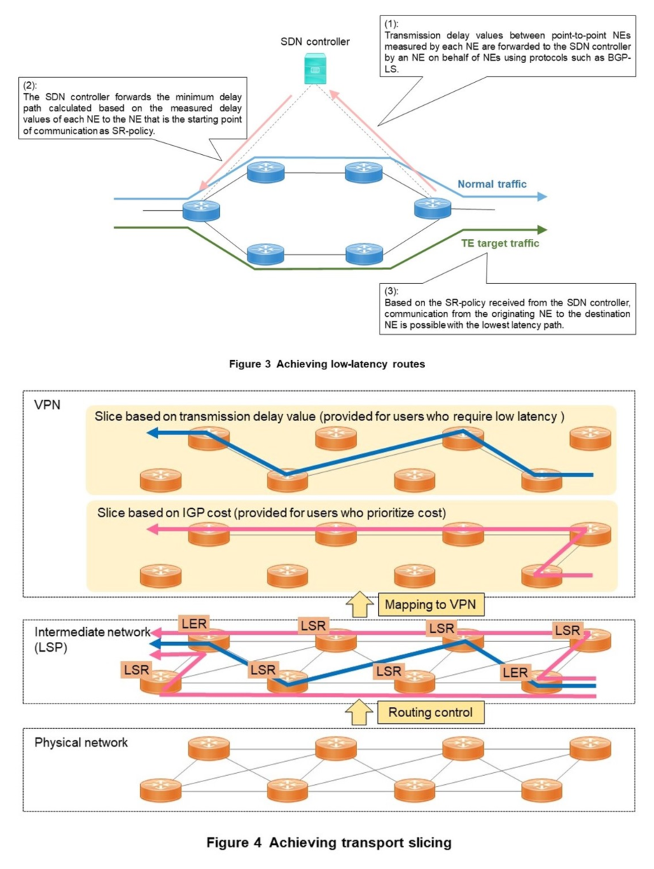
The DOCOMO transport network uses the minimum delay path based on the transmission delay values of the links collected at each NE (Figure 3).
Specifically, transmission delay values based on transmission path lengths and other factors between NEs connected point-to-point are measured by using the performance measurement function*25 based on Two-Way Active Measurement Protocol (TWAMP) Light*26 [3].
The measured transmission delay values between each NE are then normalized to a granularity on the order of several hundred microseconds and forwarded to the SDN controller (Fig. 3 (1)) described below by an NE on behalf of NEs using Border Gateway Protocol-Link State (BGP-LS)*27 [4]. The SDN controller forwards the minimum delay path calculated by its PCE function as SR-policy*28 (Fig. 3 (2)), and the NE that is the starting point of communication receives it, enabling it to select a communication path based on the transmission delay value by SR-TE in addition to the conventional Open Shortest Path First (OSPF)*29-based communication path (Fig. 3 (3)).
3) Achieving Transport Slicing
(a) Linking VPNs to LSPs
As shown in Figure 4, transport slicing is generated as a communication path based on the OSPF path cost and a communication path based on the transmission delay value by SR-TE as Label Switched Path (LSP)*30 on the physical network of the transport network. This LSP corresponds to a “slice” of the transport network. By linking a Virtual Private Network (VPN)*31 to this LSP according to the service, it is possible to provide communications that meet diverse user needs. However, transport networks do not have a mechanism to recognize the identifier that determines the network slice, such as Single-Network Slice Selection Assistance Information (S-NSSAI)*32 specified in the 3rd Generation Partnership Project (3GPP)*33. Therefore, it is necessary to select which LSP to associate a VPN with based on information in packets received from the Customer Edge (CE)*34.
In addition to the above methods, information such as the destination IP address can be used as an identifier.
(b) Anomaly detection in LSP
The NE that originates the LSP is called a Label Edge Router (LER)*35 and the NE that forwards packets to which labels are assigned is called a Label Switching Router (LSR)*36.
The LER periodically sends a probe*37 signal using the SID list received from the SDN controller to check for any anomalies in the communication path and detects that an anomaly has occurred on the SR-policy path when the communication confirmation cannot be checked at regular intervals.
In LSP, two paths, primary path and secondary path, are created in advance by calculation. Primary path is normally used. When an LSP anomaly is detected, a fast detour to the backup path is performed by Topology Independent-Loop Free Alternate (TI-LFA)*38, one of the SR-TE functions. The SDN controller then also switches to the secondary path when an anomaly is detected.
3.3 SDN Controller Deployment
1) SDN Controller Overview
As services using network slicing become more diverse in the future, it is likely that most services will be provided on-demand, in which case it will be necessary to efficiently achieve many route settings even for transport slicing using SR-TE, as described above. This requires SDN controller deployment.
Incorporating the SDN concept, transport networks are classified into two categories: NEs, which forward data, and an SDN controller, which centrally manages configuration and control [5].
The SDN controller consists of three main functions: (1) PCE function, (2) equipment configuration function, and (3) network information visualization function.
(1) PCE function
The PCE function receives requests for routes according to SR-policy from NEs using a protocol called Path Computation Element communication Protocol (PCEP)*39, calculates the path routes with the SDN controller, and then uses PCEP to communicate the calculated path routes to the NEs [6]. At this time, the SDN controller uses protocols such as BGP-LS to understand the NE topology to enable route calculation.
Typically, there is one SDN controller that manages one IGP domain*40 and calculates the routes that terminate within a particular IGP domain. However, there are extensions that allow SDN controllers to connect to each other to calculate routes passing through multiple IGP domains.
(2) Equipment configuration function
The equipment configuration function sends commands necessary for configuration to the NE from the SDN controller.
For example, by configuring VPNs for NEs, transport slicing can be achieved on a VPN-by-VPN basis.
SDN controllers are often equipped with a North Bound Interface (NBI)*41 that accepts requests from other controllers and can realize service-based transport slicing by cooperating with external systems such as service orchestrators that possess Service Level Agreement (SLA)*42 information for services.
(3) Network information visualization function
Using network information collection protocols such as Simple Network Management Protocol (SNMP)*43, the network information visualization function displays information collected from the network on a Graphical User Interface (GUI). The information displayed on the GUI includes a wide range of information such as topology status, VPN status, and the path status of the SR-TEs created. In the future, the load on the entire network should be able to be reduced by using a protocol such as Telemetry*44 that sends information unilaterally from NEs to the SDN controller, rather than a protocol such as SNMP that requires mutual communication between the SDN controller and NEs, thereby promising faster network visualization on the GUI.
2) Implementation of SDN Controller on the AR Network
On the AR network, the monitoring, control, and configuration of two types of NEs, ACR and AGR, are carried out by sharing the functions between both NE-OPS and the SDN controller. Of this division of functions, the SDN controller is responsible for the PCE function and the network information visualization function. The SDN controller of the AR network is connected to the SDN controllers in charge of networks other than the BR network as shown in Figure 5. The following effects are achieved by these configurations.
(1) Slice control function (PCE function)
Since the SDN controller on the AR network alone cannot understand the topology outside the AR network, it can only calculate routes that are completed within the AR network. By connecting SDN controllers in charge of other networks, the topology information of other networks can be known together with the AR network so that the routes of SR-TEs from the AR network to other networks can be calculated. As mentioned above, by measuring the transmission delay values between NEs using the performance measurement function, it is possible to calculate and select a route with the smallest possible transmission delay value between the AR network and other telecommunications carrier networks to pass user communications, which should contribute to low latency services.
(2) Network information visualization function
It will be possible to visualize and display topologies and VPNs from the AR network to other telecommunications carriers' networks on a GUI. This should make it possible to determine the status of transport slicing at a glance and quickly identify impacts on users of network slicing.
3) Implementation of SDN Controller on the BR Network
The SDN controller of the BR network is integrated into the NE-OPS as shown in Figure 6. Therefore, in addition to various functions such as its own NE control, the NE-OPS also has functions to manage and control slices in the BR network. Specific functions and effects are described below.
(1) Slice control function (PCE function, equipment configuration function)
Each NE on the BR network periodically measures bandwidth utilization and transmission delay values for each link and notifies the NE-OPS (SDN controller). The SDN controller uses this information to periodically calculate the optimal route in accordance with each user's SLA, and if there is a route that better meets the SLA, it instructs NEs to change the route of the corresponding SR-TE LSP in a PCEP message. This function allows the optimal communication path to be provided as needed to users who require services such as low latency, even if the conditions on the BR network change.
(2) Network information visualization function
The traffic transfer volume per link and per user on the BR network is collected periodically, and anomalies can be detected based on threshold determination. In the event of an anomaly on the BR network, maintenance personnel can go back in time to see which users and which sections (NEs or inter-NE links) are affected. External systems such as resource assurance can also retrieve traffic and alarm information collected by the NE-OPS via the NBI.
(3) Other functions (NE remote control functions, etc.)
Three routes are provided for maintenance personnel to access the BR network equipment via the Command Line Interface (CLI)*45: via an internal network line, via an external network dedicated to monitoring, or via a console server for emergency connection. Connection to all routes can be achieved by only operating the SDN controller.

- Star topology: A type of network topology. A network configuration in which multiple pieces of communications equipment connect to central communications equipment.
- IP router network: The previous generation transport network before BR network. NTT DOCOMO will systematically migrate from IP router networks to BR networks in the future.
- Partial-mesh topology: A type of network topology. A network configuration in which multiple pieces of communications equipment connect to pieces of communications equipment in a partially meshed structure.
- Virtual network: A virtual network logically independent and configured on the network using Virtual Local Area Networks (VLANs) and other techniques to separate administrative domains.
- IGP: A generic term for routing protocols used to select routes within an Autonomous System (AS).
- Metric: In this article, this refers to an indicator used for route selection in IGP.
- Path cost: The accumulated value of distance (weighting) on the path to the destination.
- SID: Segment identifier.
- PCE: Equipment that performs path calculations according to SR-policy.
- TE affinity: A technology that controls routing in TE by adding information to links, etc.
- Performance measurement function: The ability to measure conditions on a network, such as latency, so that TE metrics can be calculated.
- TWAMP Light: A protocol for measuring network quality.
- BGP-LS: A protocol for advertising link-state information in an IGP domain.
- SR-policy: A policy that specifies a forwarding route on an SR network.
- OSPF: A protocol that allows routers to select routes based on adjacent connection information.
- LSP: A one-way connection from entrance to exit.
- VPN: A virtual network logically configured for each service.
- S-NSSAI: In network slicing, an identifier used to indicate a slice on the call processing signal.
- 3GPP: An organization that creates standards for mobile communications systems.
- CE: User equipment to be accommodated on a transport network.
- LER: A router at the entrance or exit of the network where label switching is performed, and where labels are assigned or removed.
- LSR: A router, excluding LERs, that performs label switching and forwards.
- Probe: Equipment that acquires data flowing in a network and performs protocol analysis.
- TI-LFA: A function that creates a backup path without generating loops.
- PCEP: A protocol for sending a request for route calculation according to SR-policy to PCE and receiving the calculation results from PCE.
- IGP domain: The range of networks whose communication paths are controlled by a specific IGP protocol.
- NBI: In this article, this refers to a unified means of accessing SDN services and performing management tasks.
- SLA: A guarantee of the quality of a provided service.
- SNMP: Protocol that establishes an information communications method for monitoring and controlling network equipment on an IP network.
- Telemetry: Technology that collects data on equipment performance and transfers it to a remote system.
- CLI: An operating method in which all instructions to a computer or software are given in the form of text.
-
This article has described initiatives to upgrade ...
Open
This article has described initiatives to upgrade the transport network in the DOCOMO network, including network topology optimization, transport slicing using SR-TE, and the deployment of SDN controllers to efficiently achieve this.
The article also described the various benefits of introducing those technologies and systems onto the DOCOMO transport network, such as the typical example of providing lower latency routes for users who require low latency communications.
In the future, it is expected that SDN controllers on the DOCOMO transport network will cooperate with service orchestrators that control services for higher-layer users to quickly provide end-to-end network slicing services between mobile terminals and core nodes in response to service requests from users.
-
REFERENCES
Open
- [1] Y. Igaue et al.: “SR-based Routers in 5G MBH,” NTT DOCOMO Technical Journal, Vol. 23, No. 4, pp. 63-73, Apr. 2022.
 https://www.docomo.ne.jp/english/binary/pdf/corporate/technology/rd/technical_journal/bn/vol23_4/vol23_4_009en.pdf (PDF format:1,833KB)
 - [2] IETF RFC 8402: “Segment Routing Policy Architecture,” Dec. 2018.
- [3] IETF RFC 5357: “A Two-Way Active Measurement Protocol (TWAMP),” Jan. 2020.
- [4] IETF RFC 8571: “BGP-Link State (BGP-LS) Advertisement of IGP Traffic Engineering Performance Metric Extensions,” Mar. 2019.
- [5] IETF RFC 7426: “Software-Defined Networking (SDN): Layers and Architecture Terminology,” Jan. 2020.
- [6] IETF RFC 8664: “Path Computation Element Communication Protocol (PCEP) Extensions for Segment Routing,” Jan. 2022.
- [1] Y. Igaue et al.: “SR-based Routers in 5G MBH,” NTT DOCOMO Technical Journal, Vol. 23, No. 4, pp. 63-73, Apr. 2022.

