

Special Articles on 5G Evolution & 6G—Research of Radio Access Technologies Above 100 GHz toward 6G—
Propagation Simulations and Experiments in Sub-terahertz Band toward 6G
Radio Propagation 6G Sub-terahertz Band
Satoshi Suyama, Koshiro Kitao and Takahiro Tomie
6G Network Innovation Department
Mitsuki Nakamura
NTT Corporation
Abstract
Understanding radio propagation is essential to achieving stable and efficient wireless communication in a mobile communications system. This article describes the sub-terahertz band (100–300 GHz) that is expected to be used for achieving high-speed communication in excess of 100 Gbps—a key requirement of the 6G wireless network—and its radio propagation characteristics. It also introduces studies based on simulations and experiments as an NTT DOCOMO initiative toward clarifying the radio propagation characteristics of the sub-terahertz band and discusses the direction of future technology studies.
01. Introduction
-
Wireless communication from base stations to terminals in ...
Open

Wireless communication from base stations to terminals in a wireless communications system is achieved through the use of radio waves, so understanding radio propagation is essential for achieving stable and efficient wireless communication. One objective of researching radio propagation is to make it possible to infer the area that can be covered when installing a communication facility such as a base station. This is because the intensity of radio waves transmitted from a base station (the received level on the terminal side) drops with distance, so it must be made possible to evaluate the extent of this drop (path loss*1) by a channel model*2 defined by formulas or other means. The installation or removal of base stations is costly, so the research of radio propagation is an important element of a mobile communications system.
Research techniques in radio propagation include simulations such as ray tracing*3 and experiments for measuring the behavior of radio waves using measuring equipment. While requiring no measuring equipment, simulations must test the accuracy of the estimations made, so an issue here is that techniques like ray tracing require a relatively long time to complete calculations. While requiring measuring equipment as well as labor and time, experiments feature the ability to obtain highly accurate data for a given environment. It is therefore important in the research of radio propagation to perform studies by both simulations and experiments and not just by one type of technique or the other.
In this article, we explain the requirements of the 6th-Generation mobile communications system (6G) and its standardization schedule and present simulation results by ray tracing and measurement results by experiments when using the sub-terahertz band*4 (100–300 GHz) toward 6G.
- Path loss: The amount of attenuation in the power of the signal emitted from the transmitting station till it arrives at the reception point.
- Channel model: A model simulating the behavior of radio waves, used for evaluating the performance of wireless communications systems.
- Ray tracing: A method of simulating propagation characteristics by treating radio waves like light and tracing their paths.
- Sub-terahertz band: A frequency band less than a terahertz (1,000 GHz = 1 THz). In this article, it refers to the frequency band ranging from 100–300 GHz.
-
Wireless traffic in mobile terminals is increasing yearly and the amount of ...
Open
Wireless traffic in mobile terminals is increasing yearly and the amount of communication capacity that the mobile communications system must provide is likewise on an upward trend. As the successor of the 5th-Generation mobile communications system (5G) that began commercial services in 2020, the 6G next-generation system will require wireless network technology capable of speeds in excess of 100 Gbps [1]. To achieve such high-speed communications, it is thought that a variety of frequency bands including the sub-terahertz band will be needed.
Before the launch of commercial services, international standardization of a wireless system within a mobile communications system is discussed at the ITU Radiocommunication Sector (ITU-R) of the International Telecommunication Union (ITU), a specialized agency of the United Nations. In June 2022, Working Party 5D (WP 5D) of ITU-R agreed on a standardization schedule for 6G [2]. This schedule calls for completion of requirements by 2026, a deadline for proposals by around 2028, and the completion of ITU-R recommendations by mid-2030. Since technical specifications formulated by the 3rd Generation Partnership Project (3GPP) are proposed to ITU-R, full-scale standardization discussions on the 6G channel model at 3GPP are expected to begin around 2024.
-
The radio propagation characteristics*5 that must be clarified and modeled in ...
Open
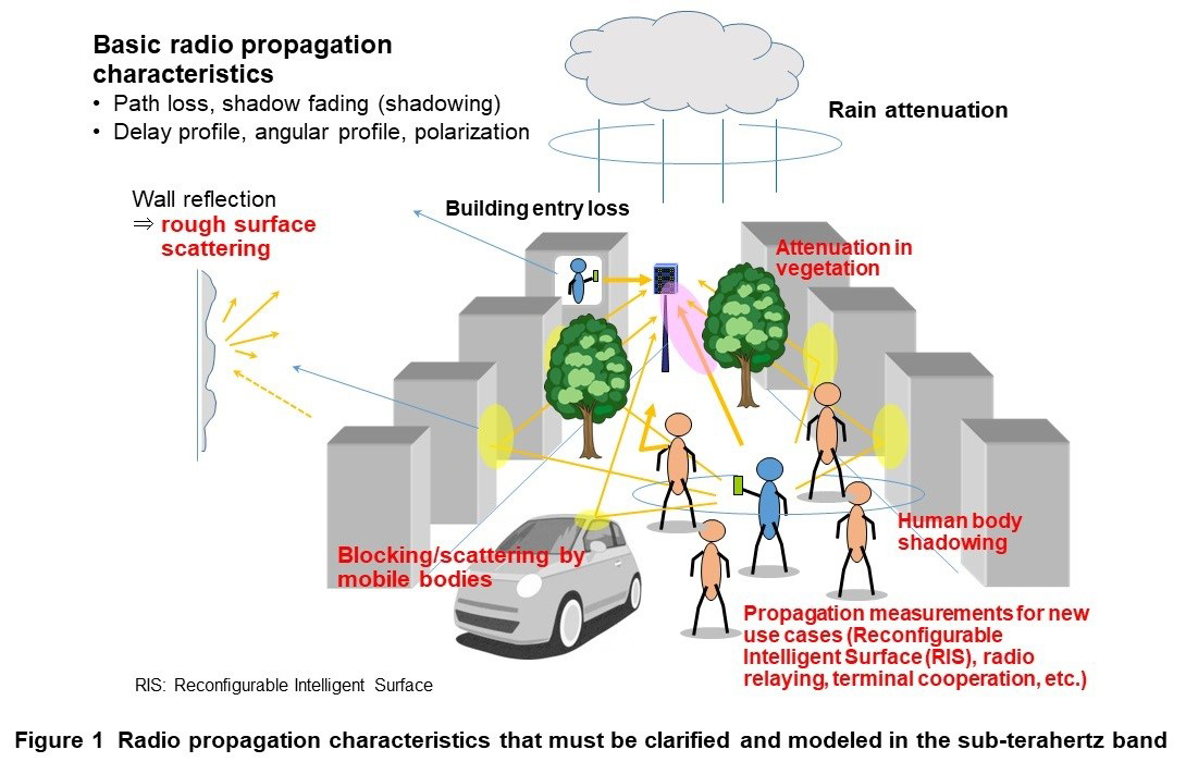
The radio propagation characteristics*5 that must be clarified and modeled in the sub-terahertz band are shown in Figure 1. In addition to featuring higher frequencies and greater path loss in comparison with the 28 GHz band used in 5G, the sub-terahertz band is also greatly affected by scattering off of walls and by blocking due to obstacles in the environment. This makes it necessary to study radio propagation characteristics such as path loss when setting out to use radio waves in the sub-terahertz band.
It has been reported that loss due to blocking by human bodies or other obstacles is greater in the sub-terahertz band compared with low-frequency bands in experiments [3]. In other words, large attenuation due to blocking can be expected when using sub-terahertz radio waves in an environment with many obstacles. However, while direct waves may be greatly attenuated by blocking, their reflected waves may nevertheless be delivered to terminals with sufficient intensity. In such a case, it should be possible to use the sub-terahertz band even in an environment with many obstacles by switching between direct and reflected waves in accordance with radio-wave blocking conditions. At NTT DOCOMO, we have conducted simulations and experiments on direct and reflected waves in the sub-terahertz band and have studied methods of using both of them [4]–[6].
3.1 Study of Radio Propagation Characteristics by Simulation
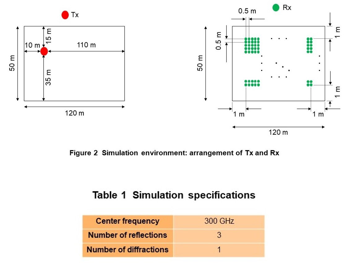
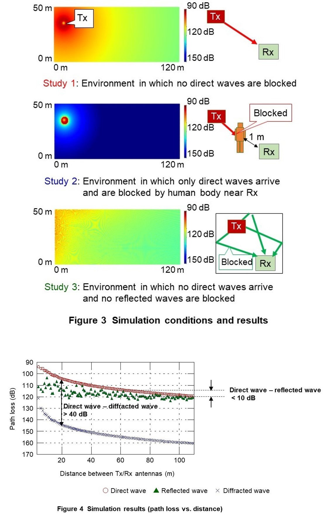
To begin with, we present the results of using ray tracing to simulate direct waves and reflected waves when direct waves are blocked for the sub-terahertz frequency of 300 GHz. Figure 2 shows the simulation environment, Table 1 lists simulation specifications, Figure 3 shows simulation conditions and results, and Figure 4 shows simulation results in terms of path loss versus distance [4].
As shown in Fig. 2, the simulation target is a space 120 m wide, 50 m deep, and 3 m high surrounded by concrete. The Transmitter (Tx) antenna is placed at a point 3 m high the same as the ceiling and at 10 m and 110 m and 15 m and 35 m from opposite wall surfaces. Next, using the point 1 m away from the two nearest walls as a base point, the Receiver (Rx) antennas are arranged at intervals of 0.5 m in parallel or at right angles to those wall surfaces at points 1 m high. As listed in Table 1, simulations were performed assuming a maximum of three reflections and one instance of diffraction with respect to the walls, the ceiling, or a human body. As shown in Fig. 3, we conducted simulations under different conditions to evaluate the effects of direct-wave blocking and reflected waves.
As shown by the color maps on the left side of Fig. 3 and by the results in Fig. 4 for distances between the Tx/Rx antennas greater than 20 m, there is a difference of approximately 40 dB or greater between direct waves that are not blocked and waves that arrive after being blocked and diffracted by a human body (diffracted waves in the figure), which is taken to be the blocking loss. On the other hand, for distances greater than 60 m, there is a difference of about 10 dB at the most between unblocked direct waves and unblocked reflected waves. This simulation therefore raises the possibility of using reflected waves at greater distances to enable communications even if direct waves happen to be blocked.
3.2 Study of Radio Propagation Characteristics by Experiment
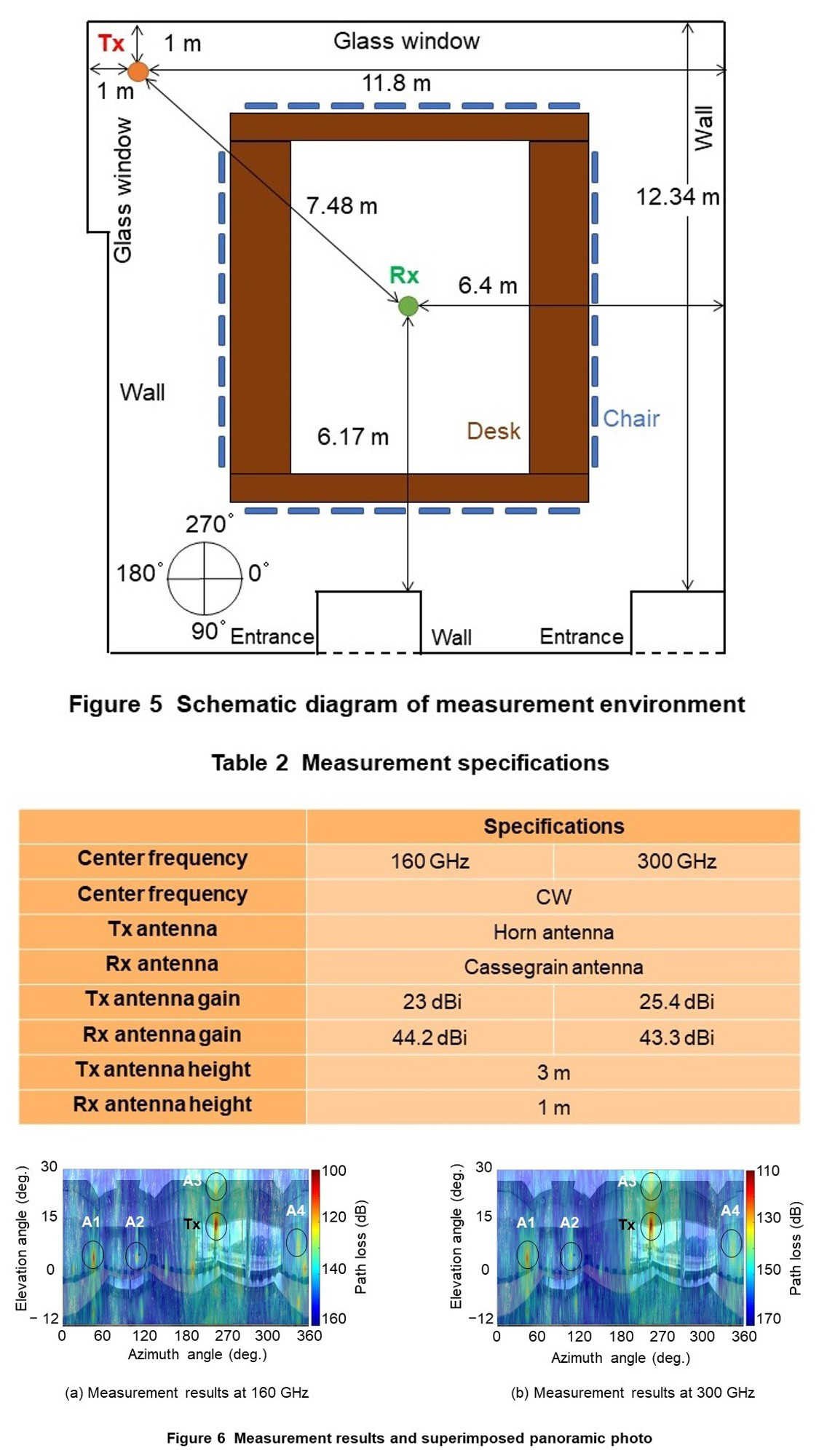
Next, we present the results of measuring path loss and arrival waves in a multipath*6 indoor environment using 160 GHz and 300 GHz as two frequencies in the sub-terahertz band. Figure 5 shows a schematic diagram of the measurement environment and Table 2 lists measurement specifications. Figure 6 shows the results of measuring path loss when varying the direction of the Rx antenna having directivity*7 both horizontally and vertically combined with a panoramic photo superimposed at the measurement point [5].
As shown in Fig. 5, the measurement environment is a space surrounded by walls or glass windows on all sides. The size of the room is approximately 12 m on each side, the height of the ceiling is approximately 3.6 m, and desks and chairs are arranged around the center of the room. Desk height and chair height are approximately 70 cm and 83 cm, respectively. As listed in Table 2, the center frequency*8 used in the measurements was of two types—160 GHz and 300 GHz—both in the form of a Continuous Wave (CW)*9 signal. For the directional antennas, we used a horn antenna*10 with a half power beam width*11 of approximately 10° for the Tx antenna and a Cassegrain antenna*12 with a half power beam width of approximately 1° for the Rx antenna. Measurements were performed with the Tx antenna placed 1 m from two intersecting walls at a height of 3 m and the Rx antenna placed at the center of the room at a height of 1 m. In these measurements, the orientation of the Tx antenna was varied in the horizontal direction from 0° to 90° (see Fig. 5) in 10° increments and in the vertical direction from -30° to 30° in 10° increments at each horizontal angle. The Rx antenna, meanwhile, was rotated 360° in the horizontal direction while its vertical direction was varied from -12° to 30° in 3° increments at each of the directions taken by the Tx antenna described above. We calculated path loss based on the received level obtained by these measurements together, the transmission power of the transmitter used in the measurements, and the Tx/Rx antenna gain*13.
In Fig. 6, the horizontal and vertical axes represent the horizontal and vertical directions, respectively, of the Cassegrain antenna on the receive side while the colors indicate path loss in each direction. Here, the path loss in the direction circled as “Tx” indicating the direction of the Tx antenna is remarkably lower compared with the surrounding area, which testifies to the fact that radio waves are arriving from that direction. Similarly, the path loss in the directions circled as A1 to A4 in the figure are remarkably lower compared with the surrounding areas, which indicates that radio waves believed to be reflected waves are arriving from those directions for either of the 160 GHz and 300 GHz frequencies. The path loss of reflected waves is about 20 dB greater than that of direct waves. From these results, it can be seen that reflected waves with a path loss 20 dB greater could arrive at the receiver even if direct waves are not available.
Based on the above, we consider that using reflectors that can suppress reflection loss and make effective use of reflected waves and high-gain antennas that can reduce the effects of path loss will be important in facilitating the use of the sub-terahertz band in 6G.
- Radio propagation characteristics: Refers to characteristics such as path loss, power and delay profiles, and angular profiles.
- Multipath: A phenomenon that results in a radio signal transmitted by a transmitter reaching the receiver by multiple paths due to propagation phenomenon such as reflection, diffraction, etc.
- Directivity: A radiation characteristic of antennas - a pattern that describes the relationship between the antenna’s electromagnetic radiation direction and the radiation intensity in that direction.
- Center frequency: The frequency within a frequency band at the center of the range used for communication.
- CW: Unmodulated continuous wave. The signal does not change, so measurements are easier to take.
- Horn antenna: A type of antenna with a cone or pyramid shape, which emits a signal that is strong in a particular direction.
- Half power beam width: The angular range over which the power emitted from an antenna goes from its maximum value to half of that value. Expresses how sharpness of the directivity.
- Cassegrain antenna: A type of antenna with a bowl shape the same as a parabolic antenna serving as the main reflector and having a sub-reflector placed between the main reflector and the direction of emission. It emits a signal that is strong in a particular direction.
- Antenna gain: A radiation characteristic of antennas – an index that describes the number of times greater the radiation intensity in the maximum radiation direction of an antenna, compared to a reference antenna.
-
In this article, we gave some background to 6G, the next-generation ...
Open
In this article, we gave some background to 6G, the next-generation mobile communications system, described examples of its requirements, explained the 6G standardization schedule going forward, and discussed the importance of researching radio propagation in a mobile communications system. We also described some of the studies conducted on the sub-terahertz band using simulations and experiments. Going forward, we plan to conduct more studies on environments involving use cases toward 6G and on scattering and blocking effects that are considered to be significant in the sub-terahertz band.
-
REFERENCES
Open
- [1] NTT DOCOMO: “5G Evolution and 6G White Paper, Version 5.0,” Jan. 2023.
 https://www.docomo.ne.jp/english/binary/pdf/corporate/technology/whitepaper_6g/DOCOMO_6G_White_PaperEN_v5.0.pdf (PDF format:4,110KB)
 - [2] ITU-R WP5D: “Attachment 2.12 to Chapter 2 of Document 5D/1361 (Meeting report WP 5D #41),” Jun. 2022.
- [3] M. Inomata, W. Yamada, N. Kuno, M. Sasaki, K. Kitao, M. Nakamura, H. Ishikawa, and Y. Oda: “Terahertz Propagation Characteristics for 6G Mobile Communication Systems,” 2021 15th European Conf. Ant. Prop. (EuCAP2021), Mar. 2021.
- [4] M. Nakamura, S. Suyama, K. Kitao, T. Tomie, and Y. Oda: “The Effect of Reflection Wave at 300 GHz-Band in Indoor Environment Simulations,” IEICE General Conference, B-1-23, Mar. 2022 (in Japanese).
- [5] M. Nakamura, S. Suyama, K. Kitao, T. Tomie, M. Inomata, W. Yamada, N. Kuno, and M. Sasaki: “Measurement of Multipath Waves at 160 GHz and 300 GHz Bands in an Indoor Environment,” IEICE Tech. Rep., Vol. 122, No. 135, AP2022-62, pp. 156–161, Jul. 2022 (in Japanese).
- [6] M. Nakamura, S. Suyama, K. Kitao, T. Tomie, M. Inomata, W. Yamada, N. Kuno, and M. Sasaki: “Measurement of Multipath Waves from 28 GHz to 300 GHz Bands in an Office Environment,” IEICE Tech. Rep., Vol. 122, No. 339, AP2022-188, pp. 62–67, Jan. 2023 (in Japanese).
- [1] NTT DOCOMO: “5G Evolution and 6G White Paper, Version 5.0,” Jan. 2023.

