

Special Articles on 5G Evolution & 6G—Research of Radio Access Technologies Above 100 GHz toward 6G—
Extreme-high-frequency-band Wireless Equipment Technology for Data Rates beyond 100 Gbps toward 6G
6G Sub-terahertz Band Wireless Equipment Technology
Atsushi Fukuda, Sumire Aoki and Yasunori Suzuki
6G Network Innovation Department
Hiroto Yamamoto and Hiroshi Hamada
NTT Corporation
Abstract
Research and development toward implementations of 6G is now being conducted worldwide. Achieving extreme-high-data-rate transmission beyond 100 Gbps as expected in 6G requires the embodiment of an extreme-wideband wireless system using an extreme-high-frequency band (sub-terahertz band) exceeding 100 GHz. However, the wireless transmission of extreme-wideband signals of several GHz and greater in the sub-terahertz band requires technologies that can compensate for the deterioration in wireless transmission performance due to imperfections in the wireless equipment. NTT DOCOMO has been researching and developing a frequency-characteristics compensation technology and a nonlinear-characteristics compensation technology as elemental technologies for the compensation of this deterioration. This article describes these technologies.
01. Introduction
-
Studies on the 6th-Generation mobile communications system (6G) ...
Open

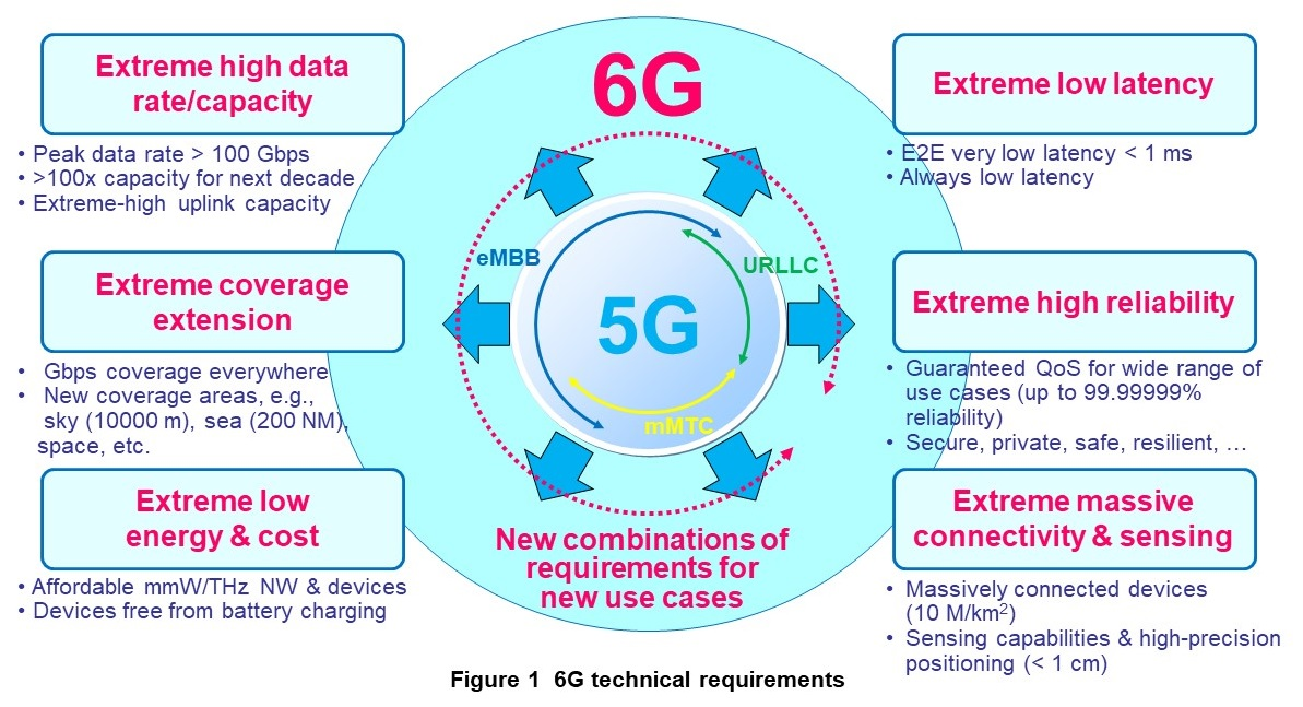
Studies on the 6th-Generation mobile communications system (6G) has been conducted worldwide. NTT DOCOMO has released “5G Evolution and 6G White Paper” that compiles a variety of use cases and technical concepts such as performance targets and elemental technologies anticipated for 6G, as shown in Figure 1 [1]. This white paper describes the need for extreme-high-data-rate communications exceeding 100 Gbps and extreme-high-capacity communications more than 100 times that of the 5th-Generation mobile communications system (5G) (total data rate per unit area). Providing communications on this level will entail more than just transmitting information based on the sense of sight and the sense of hearing as in seeing, hearing, and speaking, the norm to date. It is also expected to involve the transmission of information based on the five senses overall and on multisensory information that can convey the atmosphere of a certain place, a sense of ease, etc.
One effective means of achieving such extreme-high-data-rate and extreme-high-capacity communications is to expand the frequency bandwidth of transmission signals.
However, there are no sufficiently wide frequency bands that are available at frequencies below 6 GHz used mainly by mobile phones [2]. Thus, in 5G, attention turned to a section of the millimeter wave band, and in Japan, the 28 GHz band came to be used. In 6G, to achieve extreme-high-data-rate and extreme-high-capacity communications beyond 5G requirements, attention turned to an even higher frequency band, namely, an extreme-high-frequency band in the range of 100–300 GHz band called the sub-terahertz band. Research on the use of this band has been progressing throughout the world [3].
Against this background, the Ministry of Internal Affairs and Communications in Japan began an R&D project on the use of the sub-terahertz band in the mobile communications system. NTT DOCOMO is participating in this project, particularly research on wireless-system configuration technologies in the sub-terahertz band [4]. In this research, our target is to clarify the technologies for configuring a wireless system capable of a throughput*1 of 100 Gbps with a transmission distance of 100 m in the 100 GHz band and beyond.
One problem in wireless equipment making up such a system is that transmission quality can deteriorate remarkably due to equipment imperfections (differences that arise with respect to ideal equipment performance) that accompany higher frequencies and wider frequency bands in transmission signals. This problem due to equipment imperfections has been addressed by applying a variety of technologies. For 6G, however, preliminary studies have shown that meeting required performance by simply applying existing technologies is difficult and that the development of new technologies is needed. With this being the case, NTT DOCOMO has undertaken the research of imperfection compensation technologies for ultrawide-bandwidth*2 wireless equipment using the sub-terahertz band to achieve transmission data rates beyond 100 Gbps. In this article we describe frequency-characteristics*3 compensation technology and nonlinear-characteristics compensation technology as our main efforts in establishing imperfection compensation technologies.
This research includes some of the results from the “Research for Expanding Radio Resources (JP000254)” project commissioned by the Ministry of Internal Affairs and Communications.
- Throughput: Effective amount of data transmitted without error per unit time.
- Ultrawide bandwidth: Bandwidth of 100 MHz or greater. In Japan, 400 MHz of bandwidth has been assigned in the 28 GHz band for 5G radio communications.
- Frequency characteristics: The ratio of output amplitude to input amplitude for each frequency with respect to power.
-
2.1 Frequency-characteristics Compensation Technology
Open
1) Problem of Non-flatness in Frequency Spectrum
An effective means of achieving extreme-high-data-rate and extreme-high-capacity communications exceeding 100 Gbps is to expand the frequency bandwidth of transmission signals. According to the Shannon theorem on communication capacity as shown below, communication capacity that can be achieved increases in proportion to the frequency bandwidth.

Here, C is the communication capacity (bps), B is the frequency bandwidth (Hz), S is the signal level, and N is the noise level.
In general, a transmission signal has frequency characteristics*4, and since wireless equipment possesses frequency characteristics, the frequency characteristics of the transmission signal can be affected by the frequency characteristics of wireless equipment. As a result, non-flatness*5 can arise in the frequency characteristics of the transmission signal.
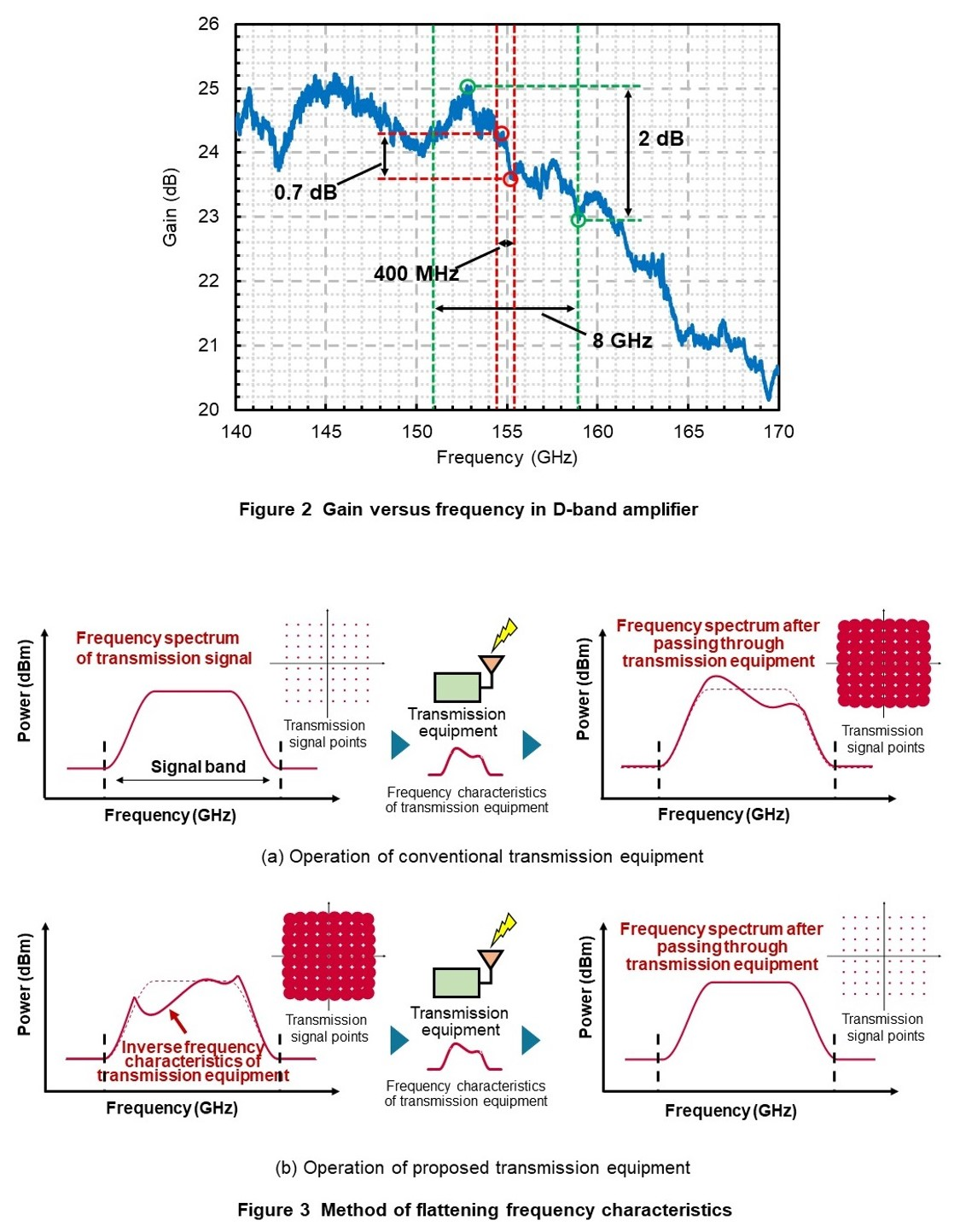
Additionally, since non-flatness becomes worse at wider bandwidths, the quality of the transmission signal can degrade even further. As an example of non-flatness arising due to bandwidth widening, Figure 2 shows gain-versus-frequency characteristics in a commercially available D-band (110–170 GHz band) amplifier*6. According to these characteristics, the non-flatness of the gain obtained when inputting a signal with a bandwidth of 400 MHz centered at 155 GHz is about 0.7 dB. In contrast, non-flatness when inputting a signal with a bandwidth of 8 GHz becomes larger at about 2 dB. In addition, given that wireless equipment incorporates many and varied components such as an amplifier, filter, and mixer, the frequency characteristics of each component are superimposed on each other. There is therefore the possibility that non-flatness within the signal band will become larger than the non-flatness of a single amplifier. This situation creates a need for frequency-characteristics compensation technology to flatten out the frequency characteristics of wireless equipment across a wide band.
2) Proposed Method
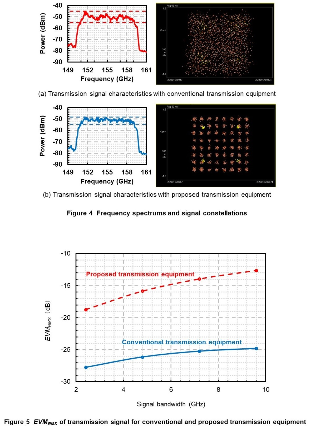
There are a variety of methods that can be used to implement frequency-characteristics compensation, but in this research, we focused on transmission equipment and proposed a method that measures the frequency characteristics of the transmission equipment beforehand, gives the inverse of those characteristics to the frequency characteristics of the transmission signal, and inputs the result into the transmission equipment [5]. The following describes the proposed method in more detail referring to Figure 3. In conventional transmission equipment, the transmission signal is input into the equipment and the transmission signal is transmitted from the equipment’s antenna with a non-flat frequency spectrum caused by the frequency characteristics of the transmission equipment. At this time, it is hard to distinguish the transmission signal points*7 of a constellation from each other due to the effects of the frequency characteristics of the transmission equipment, which degrades signal quality (produces transmission errors) (Fig. 3 (a)). In the proposed transmission equipment, inverse frequency characteristics of the transmission equipment are given to the transmission signal beforehand so that the transmission signal characteristics from the antenna caused by the frequency characteristics of the transmission equipment return to the original characteristics of the transmission signal. This method makes it easy to distinguish the transmission signal points of a constellation from each other with no deterioration in signal quality (no transmission errors) (Fig. 3 (b)).
3) Measurement Results by Experiment Using the Proposed Equipment
We conducted an experiment to evaluate the performance of the proposed frequency-characteristics compensation method when applied to 150-GHz-band transmission equipment for transmission signal bandwidths of 2.4, 4.8, 7.2, and 9.6 GHz with 64 Quadrature Amplitude Modulation (64QAM)*8. Figure 4 shows the results of measuring the frequency spectrums of the transmission signals emitted from the antennas of conventional transmission equipment and proposed transmission equipment and the associated signal constellations for a signal bandwidth of 9.6 GHz. As shown, the frequency spectrum of the transmission signal is flat for the proposed transmission equipment resulting in a state in which the signal points of a constellation can be distinguished from each other (state with no transmission errors).
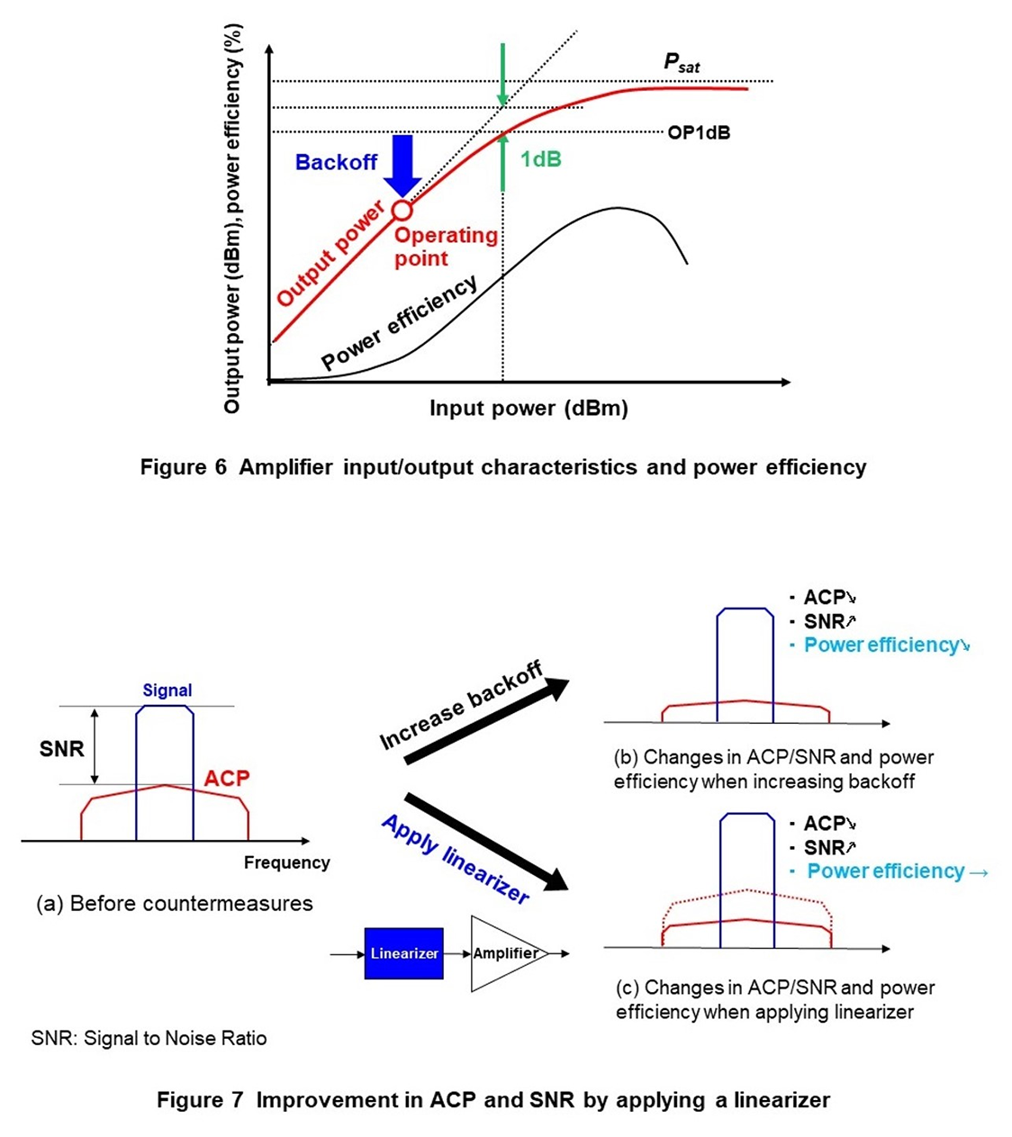
To confirm whether the quality of the transmission signal improves by the proposed transmission equipment, we performed an evaluation using an index of modulation accuracy called Error Vector Magnitude (EVM)*9 that quantifies signal quality. Figure 5 shows the results of measuring the Root Mean Square (RMS)*10 value of EVM (EVMRMS) versus signal bandwidth for the conventional and proposed transmission equipment.
EVMRMS is given by the following equation.

Here, N is the number of symbols*11, M is the number of signal points, and Sideal and Smeas are ideal signal-point positions and measured signal-point positions, respectively. For the proposed transmission equipment, it can be seen from Fig. 5 that EVMRMS improves by compensating for the non-flat frequency spectrum of the transmission signal due to the frequency characteristics of the transmission equipment. In addition, the proposed transmission equipment can improve EVM at the widest signal bandwidth of 9.6 GHz by 12.2 dB compared with the conventional transmission equipment, which shows that the improvement effect increases as the bandwidth of the transmission signal becomes wider.
2.2 Nonlinear-characteristics Compensation Technology
1) Problem of Degraded Signal Quality Due to Nonlinear Characteristics
Another problem in achieving wireless equipment for the sub-terahertz band is deterioration in the quality of the transmission signal due to nonlinear characteristics of the components making up the transmission equipment. Nonlinear characteristics refer to change in component performance (such as gain) that was originally desired to be constant with respect to the amount of power input into (output from) a constituent component. This change produces problems. For example, the waveform of the modulated signal can deteriorate preventing it from being sufficiently detected at the receiver, or unwanted radiation*12 can occur in other signal bands used in communications (such as Adjacent Channel Leakage Power (ACP)*13). In general, the linearity of constituent components in the sub-terahertz band is low compared with lower frequency bands, which is thought to be the reason why nonlinear characteristics can easily become large.
The relationship between amplifier input/output characteristics (output power with respect to input power) and power efficiency is shown in Figure 6. Here, it can be seen that output power within the range of small input power is proportional to input power. However, as input power increases, the nonlinear characteristics of the amplifier become noticeable and the increase in output power gradually diminishes eventually reaching saturation.
One index of an amplifier’s linearity is the output 1dB compression point (OP1dB) that indicates the amplifier’s output power value 1 dB below its ideal output. It can be said that an amplifier with high OP1dB has characteristics closer to the ideal.
If the amplifier is used near OP1dB or saturation output (Psat), the signal input to the amplifier will be greatly distorted, so the usual approach is to operate the amplifier at a level of power below OP1dB by only a backoff amount as shown in Fig. 6. However, as shown in the figure, power efficiency drops for larger amounts of backoff, so achieving transmission equipment with low power consumption is difficult.
2) Compensation of Nonlinear Characteristics by a Linearizer
We study the use of a linearizer*14 as a circuit typically used in an amplifier as a constituent component to compensate for nonlinear characteristics. As shown in Figure 7, a linearizer is placed at the stage preceding the amplifier as an element that compensates for the nonlinear characteristics of the amplifier. In this way, the linearity of the linearizer and amplifier as a composite element enables OP1dB to be improved and the amount of backoff to be decreased.
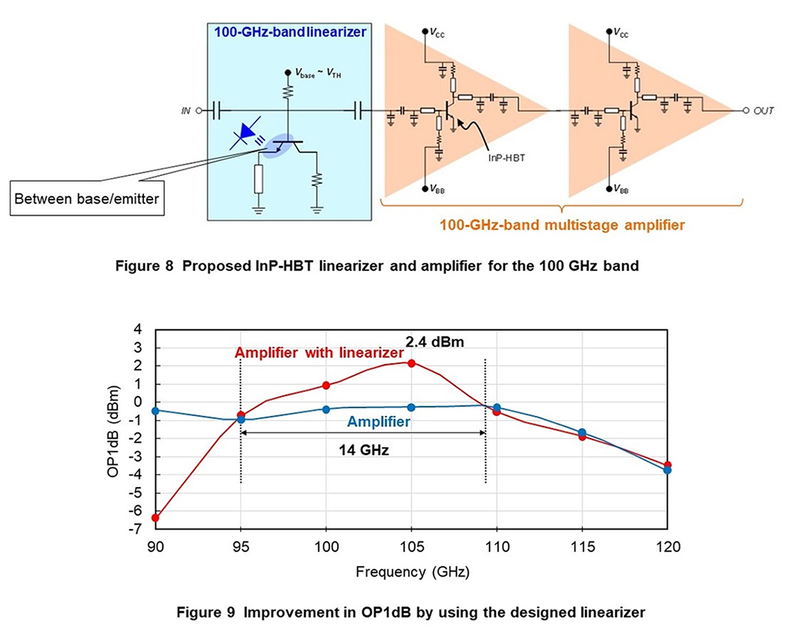
The proposed circuit diagram of the linearizer and amplifier for the 100 GHz band is shown in Figure 8. In this circuit design, we used an Indium Phosphide-Heterojunction Bipolar Transistor (InP-HBT)*15 having excellent high-frequency characteristics. The design gain of the multistage amplifier is 20 dB in the 100 GHz band and OP1dB is –0.4 dBm. Here, we applied a scheme that suppresses the nonlinear characteristics of the amplifier by using a diode*16 having inverse nonlinear characteristics with respect to the nonlinear characteristics of the amplifier. Specifically, we configured the linearizer by inserting such a diode having inverse nonlinear characteristics between the InP-HBT’s base*17 and emitter*18 as shown in Fig. 8. Simulation results of OP1dB for the amplifier alone and the linearizer-equipped amplifier are shown in Figure 9. It can be seen from this simulation that OP1dB improves in the 95–109 GHz range by using this linearizer thereby confirming the effectiveness of using a linearizer in the sub-terahertz band. There have been few studies on the use of linearizers in the sub-terahertz band, and this research was selected for presentation at Asia-Pacific Conference on Communications (APCC) 2022 where it received a Best Paper Award [6].
- Frequency characteristics: The relationship between frequency and power at each frequency.
- Non-flatness: Indicates the presence of fluctuation within a certain frequency band.
- Amplifier: A circuit that amplifies the signal.
- Transmission signal points: The representation of a transmission signal by individual points on the real and imaginary axes.
- 64QAM: A digital modulation method that enables the simultaneous transmission of 6 bits of information by assigning one value to each of 64 different combinations of phase and amplitude.
- EVM: An index of communication quality indicating the magnitude of error with respect to the original signal point.
- RMS: A statistical term. In this article, it refers to an index expressing the magnitude of an electrical signal.
- Symbol: In this article, the smallest unit of transmitted data. In Quadrature Phase Shift Keying (QPSK), for example, there are two bits of information per symbol.
- Unwanted radiation: The emission of unnecessary radio waves in communications.
- ACP: Power emitted to an adjacent position in a signal band due to nonlinear characteristics of a circuit, etc.
- Linearizer: A functional component that linearizes the nonlinear characteristics occurring in a device.
- InP-HBT: An HBT that uses InP substrates.
- Diode: An electronic device having the effect of conducting current in one direction (rectifying effect).
- Base: One of the three terminals (emitter, base, collector) of a bipolar transistor having the role of controlling the current flowing between the emitter and collector.
- Emitter: One of the three terminals (emitter, base, collector) of a bipolar transistor having the role of supplying the transistor with the electrons needed for amplification.
-
In this article, we described frequency-characteristics compensation technology ...
Open
In this article, we described frequency-characteristics compensation technology and nonlinear-characteristics compensation technology as our main efforts in the development of technologies that can compensate for the imperfections in wireless equipment used for extreme-wideband transmission. Going forward, our plan is to implement these technologies in transmitters.
-
REFERENCES
Open
- [1] NTT DOCOMO: “5G Evolution and 6G White Paper, Version 5.0,” Jan. 2023.
 https://www.docomo.ne.jp/english/binary/pdf/corporate/technology/whitepaper_6g/DOCOMO_6G_White_PaperEN_v5.0.pdf (PDF format:4,110KB)
 - [2] Ministry of Internal Affairs and Communications: “Current Situation of Spectrum Use in Japan.”
 https://www.tele.soumu.go.jp/e/adm/freq/search/myuse/index.htm
 - [3] W. Saad, M. Bennis, and M. Chen: “A Vision of 6G Wireless Systems: Applications, Trends, Technologies, and Open Research Problems,” IEEE Network, Vol. 34, No. 3, pp. 134–142, May/Jun. 2020.
- [4] Ministry of Internal Affairs and Communications: “R&D of Communication Devices for High Frequency Bands Exceeding 100 GHz,” Research and Development for Expansion of Radio Wave Resources, Handbook of R&D Projects, Mar. 2022 (in Japanese).
https://www.tele.soumu.go.jp/resource/j/fees/purpose/pdf/r3kenkyukaihatsu.pdf#page=13 - [5] H. Yamamoto, A. Fukuda, S. Aoki, H. Hamada, H. Okazaki, and Y. Suzuki: “Wideband Single Carrier Transmitter Configuration Equalizing Non-flat Frequency Response,” 2022 27th Asia Pacific Conference on Communications (APCC), pp. 209–213, Oct. 2022.
- [6] S. Aoki, H. Hamada, H. Yamamoto, A. Fukuda, T. Jyo, H. Takahashi, H. Okazaki, and Y. Suzuki: “A Design of InP-HBT 100-GHz Diode Linearizer Toward 6G,” 2022 27th Asia Pacific Conference on Communication (APCC), pp. 140–144, Oct. 2022.
- [1] NTT DOCOMO: “5G Evolution and 6G White Paper, Version 5.0,” Jan. 2023.

